

Genie Slide Gate Operator Maintenance Schedule & Troubleshooting Guide
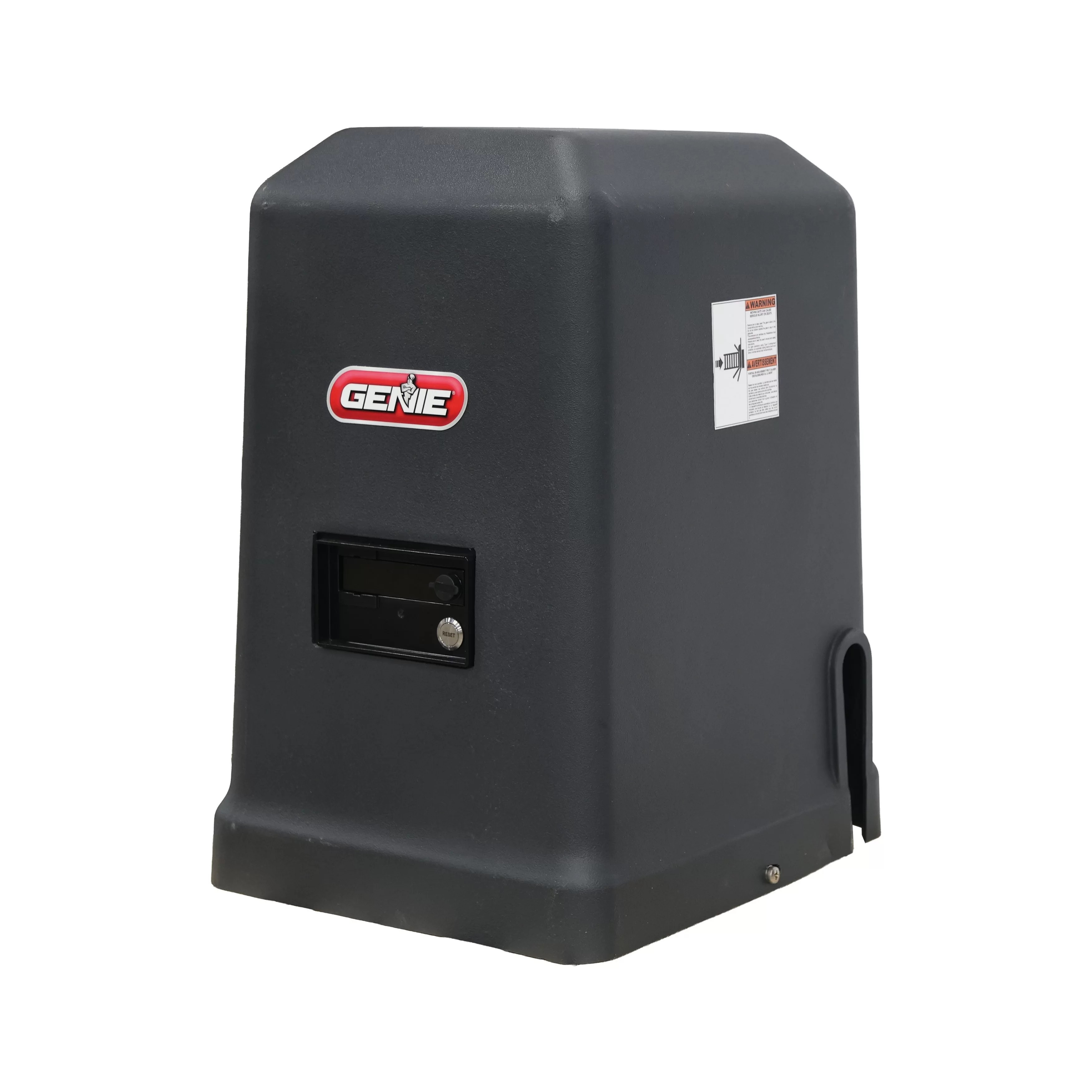
Keeping your Genie slide gate operator on a regular maintenance schedule is the easiest way to avoid unexpected downtime. Below is a quick-reference guide drawn from the official Genie installation and operation manuals, with direct links to the full PDFs so you or your technician can jump straight to the source. This guide applies to: GCSL36V (Commercial 36V Slide Gate Operator) & GRSL24V (Residential 24V Slide Gate Operator)
Reference Manuals
Control Board LED Meanings
The control board uses status LEDs as a first-step diagnostic tool. While every issue should be confirmed with a voltmeter, the LEDs will point you in the right direction before you open the troubleshooting charts. Based on the Linear/GTO DC slide control-board design used in this product family, here is what the LEDs indicate:
| LED | State | Meaning |
|---|---|---|
| Green | Solid ON | The control board is receiving power from the transformer (or solar supply). |
| Red | Dim/Steady ON | Normal standby state. This light also assists during transmitter programming. |
| Red | Flashing | Low voltage lockout. The battery or charging source is too low to operate the gate. |
Important: If you see a flashing red LED, check all charging connections and test the battery under load before replacing any parts. The full LED-driven diagnostic steps are located in the Troubleshooting section (pages 49-55) of each manual.
Maintenance Schedule
The Maintenance section on page 59 of each manual lists the service tasks required to keep the operator UL325-compliant and running smoothly. Based on the related GTO/Linear slide-operator maintenance protocol, your routine should look like this:
| Frequency | Task |
|---|---|
| Monthly | Test the operator. The gate must reverse on contact with an obstruction or when non-contact sensors are activated. If it does not, discontinue use and have the operator serviced immediately. |
| Quarterly | Inspect and lubricate the drive chain; check gear sprockets and grease as needed. Use a quality chain-and-cable lubricant. |
| Quarterly | Check that the gate is level and plumb; verify guide rollers spin freely and are greased with a lubricant rated for your coldest local weather. |
| Quarterly | Test all safety edges/entrapment protection devices. Replace any device that fails to function. |
| Annually | Inspect electrical connections, battery terminals, and wiring inside the control box. Keep terminals clean and tight. |
| As Needed | Place a few mothballs inside the control box to discourage insects from nesting on the board. |
Safety Note: The manual stresses that a qualified service person should perform gate hardware repairs. Do not attempt to force the gate or bypass safety devices.
Common Troubleshooting Issues
Both manuals dedicate pages 49-55 to a step-by-step troubleshooting table. Rather than reprinting the full charts, here are five of the most common issues you will find in those pages, along with the page references for the complete procedures.
1. Gate Will Not Operate/No Respons
Typical causes: AC power interruption, low battery, blown control-board fuse, limit-switch misalignment, or a triggered safety accessory locking out the system. See GCSL36V & GRSL24V Manuals, pages 49-50.
2. Gate Begins to Move, Then Stops and Reverses
Typical causes: Sensitivity set too high, an obstruction in the gate path, binding guide rollers, or an activated reversing edge / photo-eye during travel. See GCSL36V & GRSL24V Manuals, pages 50-51.
3. Gate Operates Very Slowly or Stops Before Finishing the Cycle
Typical causes: Low battery voltage (most common), insufficient charging from the transformer or solar panel, or excess mechanical load caused by poor alignment. See GCSL36V & GRSL24V Manuals, pages 51-52.
4. Control-Board 15-Amp Fuse Blows When a Command is Given
Typical causes: Gate physically binding so the motor cannot turn, incorrect limit-switch setting causing the motor to stall, or a short in the low-voltage actuator wiring. See GCSL36V & GRSL24V Manuals, pages 52-53.
5. Remote Transmitter Will Not Operate the Gate
Typical causes: Dead transmitter battery, mismatched dip-switch settings between transmitter and receiver, a stuck receiver relay, or a safety input that is active and blocking remote commands. See GCSL36V & GRSL24V Manuals, pages 53-54.
Browse Our Openers
If you have any further questions, please reach out to our representatives. They are happy to help in any way they can!
Contact Us